Custom Sensorless BLDC ESC for E-bike Applications
Project Overview
This project demonstrates the design and implementation of a custom Electronic Speed Controller (ESC) for brushless DC motors in e-bike applications. The goal was to create an integrated solution combining motor control with e-bike-specific features like throttle input, brake lighting, and safety systems while maintaining cost, effectiveness and reliability.
Understanding BLDC Motors and Control Challenges
Brushless DC (BLDC) motors operate using three electromagnetic phases (A, B, C) that must be energized in precise sequence to create rotating magnetic fields. Unlike brushed motors, BLDC motors require electronic commutation ,knowing exactly when to switch between phases for optimal efficiency and smooth operation.
Traditional solutions use Hall sensors to detect rotor position, but this adds cost, wiring complexity, and potential failure points. My approach uses back-EMF detection, reading the voltage generated by the motor’s own rotation to determine position. This “sensorless” method eliminates sensors while maintaining precise control.

System Architecture
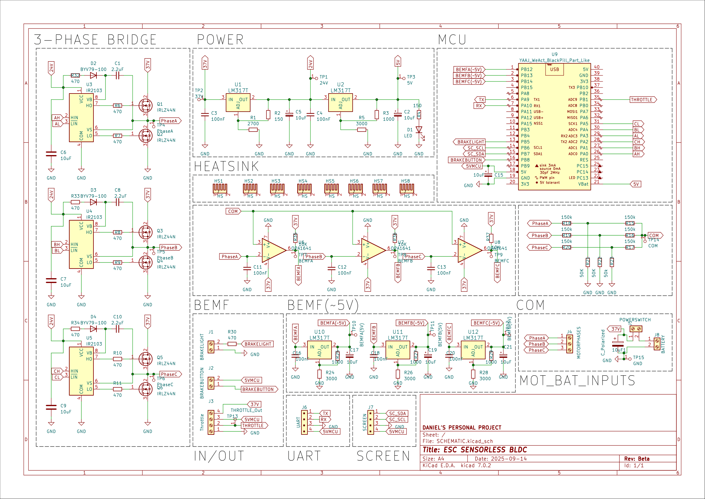
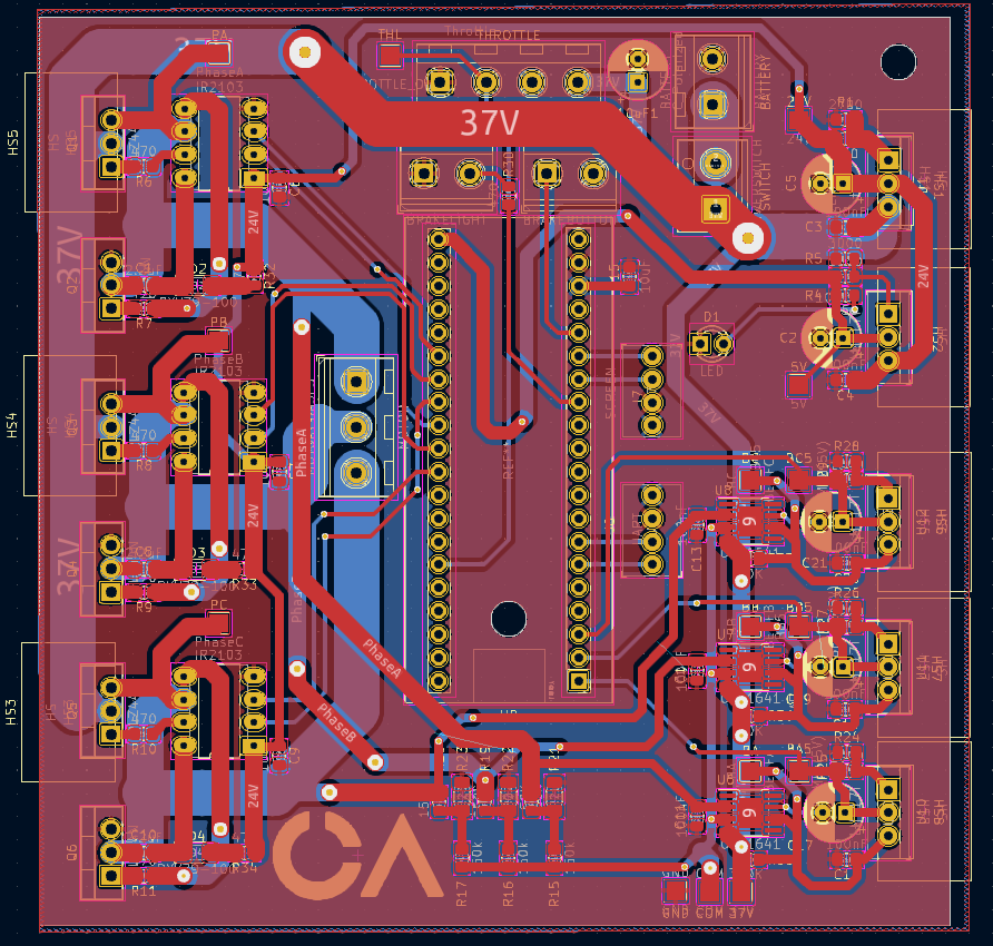
Hardware Design Blocks
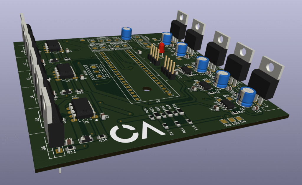
Power Stage: Six-MOSFET three-phase bridge converts DC battery voltage into controlled three-phase AC for the motor. Gate drivers ensure proper MOSFET switching timing and protection.
Control Unit: STM32 microcontroller processes sensor inputs, executes control algorithms, and generates precise PWM signals for motor commutation.
Back-EMF Detection: Voltage divider networks and comparators monitor undriven motor phases to detect zero-crossing events, providing rotor position feedback without physical sensors.
Interface Systems: Analog inputs for throttle control, digital inputs for brake sensors, and outputs for auxiliary systems like brake lights and status indicators.
These blocks work together in a coordinated control loop: the throttle provides speed commands, back-EMF detection provides position feedback, and the control unit orchestrates the power stage to achieve desired motor behavior.
Results and Lessons Learned
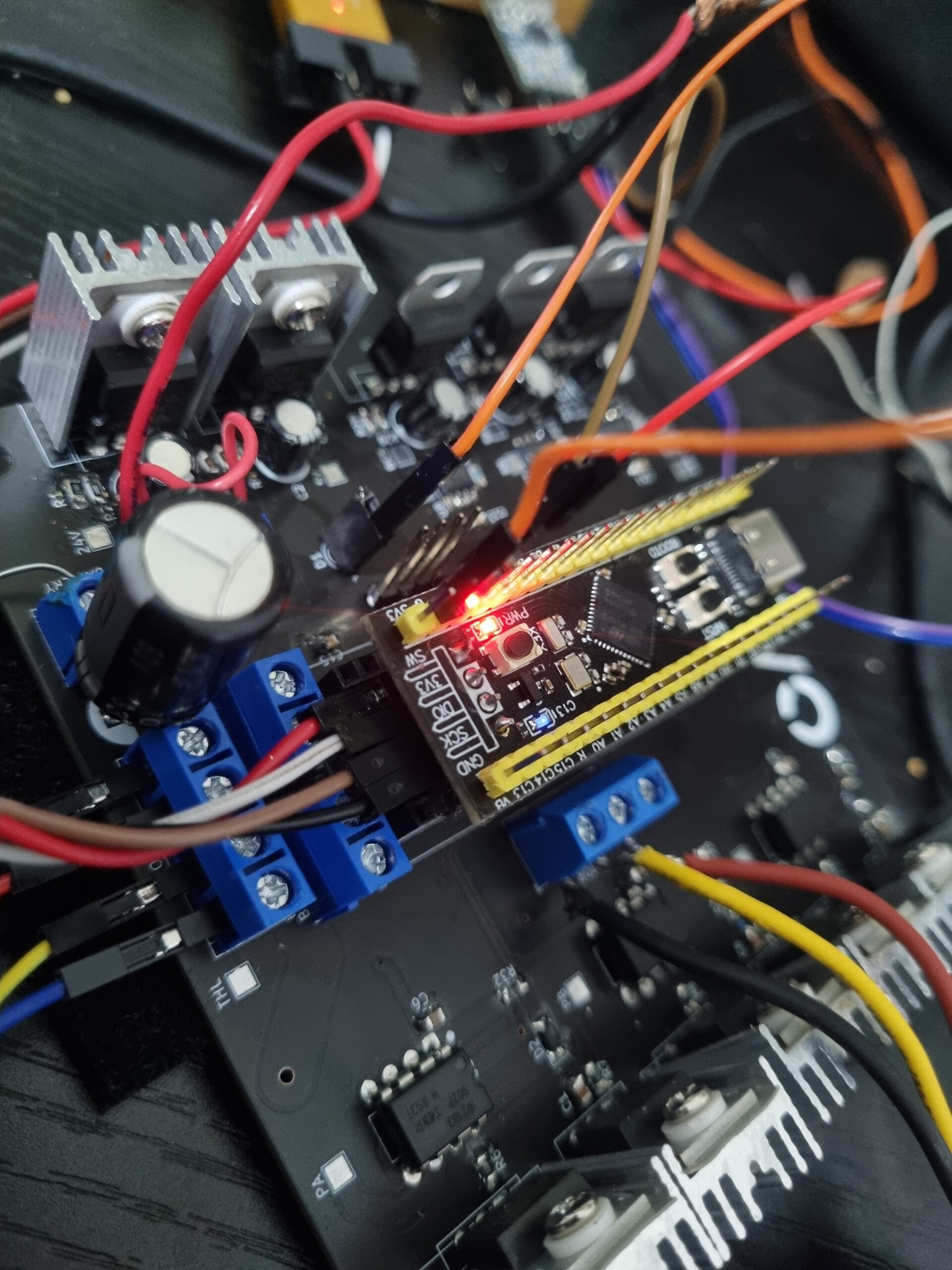
The first prototype successfully demonstrated the concept the motor ran smoothly with good speed control and integrated e-bike functions operated as designed. However, one PCB literally went up in flames during testing, highlighting thermal management challenges.
The custom schematic design represents a solid attempt at balancing simplicity and performance while keeping assembly costs low. Although there are areas for improvement, and some bypassing for extra current limiting resistors was implemented during soldering, the overall design successfully demonstrates the core concepts. After evaluating many existing designs that had either limiting factors or lacked reliability, this approach prioritized practical functionality over theoretical perfection.
Future Improvements
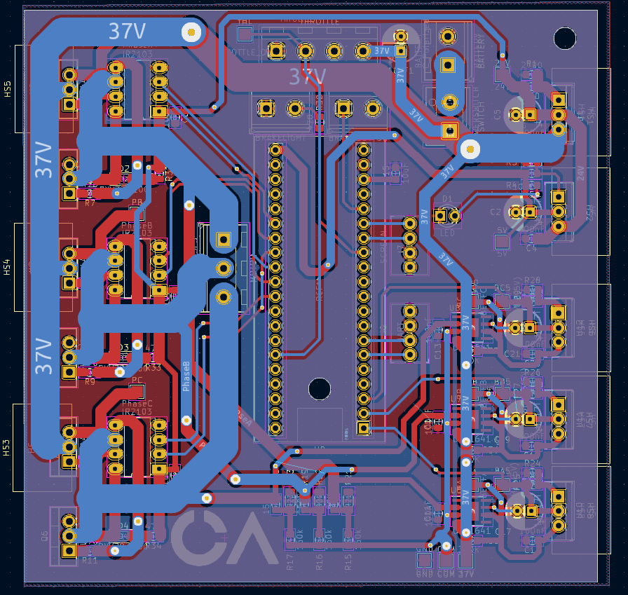
Thermal Management: Better heat dissipation through improved heatsink design and PCB thermal layout.
Power Efficiency: Implement switching-mode voltage regulation instead of linear regulators that dissipate excess energy as heat.
Robustness: Enhanced protection circuits and more conservative current ratings for sustained operation.
Technical Impact
This project showcases end-to-end embedded systems development – from circuit design and PCB layout through firmware implementation and system integration. The sensorless approach reduces system complexity while the integrated e-bike features demonstrate practical application focus. Most importantly, the lessons learned from the thermal failure provide valuable insights for future high-power electronics design.
The project successfully bridges theoretical motor control concepts with real-world implementation challenges, demonstrating both technical competency and practical engineering judgment essential for robotics development.